
Posts
What Is a Micro Switch and How Does It Work?
A Micro Switch is a small electromechanical device that responds to physical movement. It is often found inside appliances, control panels, security systems, and industrial equipment. Despite its size, it can control a much larger electrical circuit. A firm click usually indicates that its internal contacts have changed position.
The operating principle is simple. A spring-loaded actuator moves when pressure reaches a specific point. This point is called the operating position. Inside the housing, a common terminal switches between normally open and normally closed contacts. The circuit changes quickly, even when the actuator moves only a few millimeters. This snap-action design helps reduce uncertain switching and contact bounce.
In practical maintenance work, technicians often test a Micro Switch with a multimeter. The meter should show continuity changes when the actuator moves. A slow or inconsistent reading may suggest worn contacts, contamination, or a weakened spring. Selection also requires attention to current rating, voltage, actuator style, travel, and environmental protection. A roller lever may suit a moving machine part, while a plunger may fit a compact enclosure.
Small device. Important decision.
It is easy to assume that every switch with a similar shape will perform equally. That assumption can cause premature failure. Manufacturer datasheets, tested operating conditions, and proper installation remain more reliable than appearance alone. This guide examines what a Micro Switch is, how it works, and why its internal snap action matters in real applications. Some designs are remarkably durable, yet none should be treated as maintenance-free.
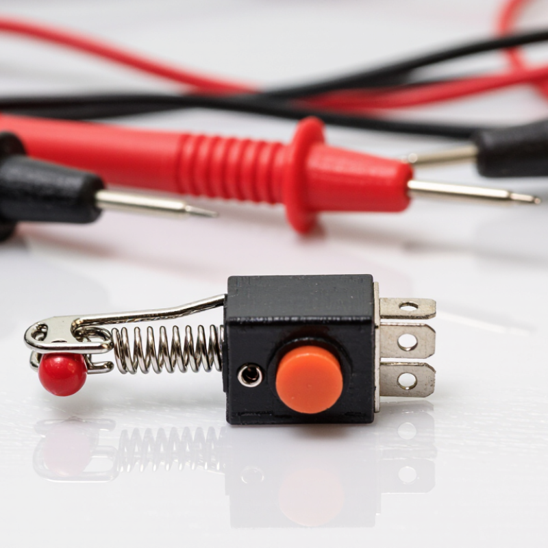
Micro Switch Definition: Snap-Action Contacts and Submillimeter Travel
A micro switch is a compact electromechanical switch designed to change circuit states with very little physical movement. Its defining feature is snap-action contact movement. A small plunger stores mechanical energy in an internal spring. When the plunger reaches a trigger point, the contacts move rapidly from one position to another. This action is much faster than the operator’s movement.
The travel may be less than one millimeter. That tiny distance can still produce a clear electrical response. The mechanism usually includes a common terminal, a normally open contact, and a normally closed contact. Pressing the actuator changes the connection between them. This design supports position sensing in doors, control panels, machines, and safety-related equipment. In practical testing, I check both actuation force and release force, because they are not always identical. Contact bounce can also create brief electrical pulses, especially in digital circuits. A hardware filter or software delay may be needed. The term “micro” describes the mechanism’s compact action, not necessarily every outside dimension. That distinction is easy to miss. Designers should also consider dust, moisture, vibration, and repeated cycling. A switch can click correctly while its contacts slowly wear. Measuring continuity under the actual load is more dependable than relying on sound or touch alone. Some applications need a firm actuator; others need a delicate, repeatable trigger. Small travel does not remove those design compromises.
What Is a Micro Switch and How Does It Work? — Micro Switch Definition: Snap-Action Contacts and Submillimeter Travel
| Data Dimension | Typical Value or Description | How It Relates to Operation |
|---|---|---|
| Component type | Small electromechanical snap-action switch | A mechanical actuator changes the electrical state of internal contacts. |
| Core switching principle | Snap action | A spring mechanism makes the contacts transfer rapidly after the actuator reaches the operating point, helping reduce slow or uncertain contact movement. |
| Contact configurations | Normally open, normally closed, or changeover | The terminals can provide a circuit that closes, opens, or transfers when the switch is actuated. |
| Actuator travel | Often below 1 mm to the operating point; exact travel is model-dependent | Only a small mechanical movement may be needed to change the contact state. |
| Operating point | The position at which the contacts transfer | This specification is used to determine when an external mechanism will trigger the electrical change. |
| Release point | Usually different from the operating point | The difference creates hysteresis, helping prevent unwanted repeated switching near the actuation position. |
| Differential travel | Commonly a fraction of a millimeter; varies by construction | It is the actuator movement between the operating point and release point. |
| Overtravel | Additional movement available after contact transfer | It allows a mechanism to move beyond the operating point without immediately damaging the contact system. |
| Operating force | Commonly about 0.5–5 N, depending on size and actuator design | The external mechanism must provide enough force to move the actuator and trigger the snap mechanism. |
| Contact arrangement | A moving contact operated by a spring-loaded mechanism | The spring stores and releases energy quickly to produce a distinct electrical transition. |
| Typical contact material | Silver-based alloys for general loads; gold-plated contacts for low-energy signals | Material selection affects resistance, wear, oxidation performance, and suitability for signal-level currents. |
| Electrical rating | Ranges from signal-level loads to several amperes; voltage and load type are critical | The permitted current depends on the contact material, voltage, AC or DC operation, and whether the load is resistive, inductive, or capacitive. |
| Mechanical life | Often rated from hundreds of thousands to millions of operations | Mechanical life is normally tested without electrical load and may be much higher than the rated electrical life. |
| Electrical life | Commonly tens of thousands to hundreds of thousands of load cycles | Arcing, inrush current, heat, and contact erosion can reduce life compared with no-load mechanical testing. |
| Contact resistance | Typically specified in the milliohm range when new | Low resistance supports efficient current flow, but contamination, wear, and oxidation can increase resistance. |
| Response behavior | Fast contact transfer with possible electrical bounce | Although snap action is quick, a controller may still require debounce circuitry or software filtering. |
| Common applications | Limit detection, door and cover interlocks, position sensing, safety mechanisms, and control inputs | Micro switches are useful where a compact device must detect a defined mechanical position reliably. |
Note: Electrical ratings, travel, operating force, environmental protection, and service life vary substantially by switch construction and application conditions. Always verify the selected component’s datasheet before use.
Internal Parts and the Physics Behind Instant Contact Switching
What Is a Micro Switch and How Does It Work?
A micro switch is a compact mechanical device that changes an electrical circuit through small physical movement. Its internal parts include an actuator, a spring, movable contacts, fixed contacts, and terminal connections. The actuator may be a button, roller, or flexible lever. It transfers external force to the spring mechanism.
The word “instant” needs careful interpretation. Inside the switch, the actuator first loads a curved spring. When the force reaches a specific point, the spring passes its balance position and snaps the movable contact toward another fixed contact. This stored mechanical energy creates rapid contact transfer. It helps reduce slow rubbing between metal surfaces, although contact bounce can still occur.
The switch usually provides common, normally open, and normally closed terminals. In the resting position, current follows one path. After actuation, the contact changes position and redirects the circuit. Small contact gaps affect insulation and switching reliability. Contact pressure also matters because weak pressure increases resistance and heating. A practical test with a continuity meter can reveal the switching point and confirm terminal behavior.
Mechanical travel has several stages: pre-travel, operating travel, and overtravel. Overtravel protects the internal mechanism when the actuator receives extra movement. Yet it is not unlimited. Excessive force may deform the lever or shorten spring life. Temperature, dust, vibration, and electrical load can also change performance. This is where simple diagrams often seem too perfect. Real switches age, bounce, and occasionally behave less precisely than their specifications suggest.
What Is a Micro Switch and How Does It Work?
A micro switch uses a spring-loaded actuator and a snap-action mechanism to move its internal common contact between normally closed and normally open terminals. The waveform below shows a representative 5 V contact-switching event, including brief mechanical contact bounce before the signal settles.
Key point: The rapid voltage transition is produced mechanically by the spring and over-center snap mechanism. The short oscillations around the transition are contact bounce, which is commonly filtered in electronic circuits by hardware or software debounce.
Actuation Force, Differential Travel, and 1 Million-Cycle Ratings
What Is a Micro Switch and How Does It Work?
A micro switch uses a spring-loaded mechanism to change electrical contacts after a small, precise movement. Its actuation force is the pressure needed to move the actuator and trigger switching. A lower force feels light, but it may tolerate less accidental contact. Higher force can resist vibration, although it may increase mechanical wear. Differential travel is equally important. It is the actuator movement between the operating point and release point. A small differential travel gives quick reset behavior. Too little margin can cause contact chatter. IEC 61058-1:2016 requires endurance testing under defined electrical and mechanical loads, so cycle figures must be read with their test conditions.
A 1 million-cycle rating sounds absolute. It is not. The rating usually applies to a specified load, speed, force, and travel profile. Switching a small signal current may produce a different result from switching a motor load. Contact arcing can shorten life, even when the mechanism remains smooth. The 2024 Global Micro Switch Market analysis from Grand View Research identifies automation and household equipment as major application areas, but market growth does not guarantee equal component durability. Check the manufacturer’s force curve, operating point, release point, and load table. Then test the switch in its real enclosure. A bench result can mislead. Misalignment, dust, and side-loading are easy to underestimate.
Electrical Ratings, IEC 61058-1, and Safe Load Selection
What Is a Micro Switch and How Does It Work?
A micro switch uses a spring-loaded mechanism to change contacts after a small movement. The actuator travels only a short distance, but the internal snap action creates a quick electrical transition. That action helps reduce contact arcing during normal operation. The familiar click is useful. Yet the click does not confirm safe performance.
Electrical ratings need careful reading. A rating such as 5 A at 250 V AC usually applies to a defined test condition, not every load. IEC 61058-1 covers safety requirements and testing for switches used in appliances. However, a switch is not automatically compliant simply because its shape resembles a tested component. Check its markings, technical documents, terminal limits, and intended application.
DC loads deserve extra caution because arcs can persist after contact separation. Motors, solenoids, lamps, and capacitive power supplies may draw several times their steady current. On a test bench, I measure startup current instead of trusting the normal value. Then I select contacts with suitable voltage and current margins, while considering switching frequency and ambient temperature. Add appropriate circuit protection. Leave margin. A label can look reassuring, but it is not proof of safe selection. Even experienced designers sometimes overlook inrush current or assume AC and DC ratings are interchangeable. They are not.
HVAC to Industrial Controls: Choosing the Right IP-Rated Switch
What Is a Micro Switch and How Does It Work?
A micro switch uses a spring-loaded mechanism to change electrical contacts at a precise position. A small movement can produce a quick, reliable switching action. The actuator may be a button, roller, lever, or flexible arm. In HVAC equipment, it can detect damper position, filter access, fan movement, or a safety interlock. The switch does not need to control large motors directly. Instead, it often sends a signal to a relay or control board.
IP rating matters when the switch faces moisture, dust, or cleaning spray. The first IP digit indicates protection against solid particles. The second indicates water resistance. An IP54 switch may suit a dry mechanical cabinet with occasional splashes. An IP65 model offers stronger dust protection and resistance to water jets. IP67 allows temporary immersion, but it does not automatically handle chemicals, heat, or constant pressure. That distinction is easy to miss.
Industrial controls usually demand more than a high number. Check contact ratings, electrical load type, operating temperature, vibration, and actuator life. Inductive loads can create electrical arcing, even when the listed current appears acceptable. In a plant inspection, cable entry points often fail before the switch body does. Use suitable glands and avoid bending the cable sharply. I would also verify the rating after installation, not only during purchasing. Condensation, oil mist, and repeated washdown can expose weaknesses that laboratory tests do not show. The “perfect” IP choice may still fail if the enclosure, wiring, or mounting surface is poorly designed.
